// test_DS1820
#include
float celsius, fahrenheit;

OneWire  ds(10);  // on pin 10

void setup(void) {
  Serial.begin(9600);
}


void loop(void) {
  celsius = ReadTempDS1820();
  if (celsius!=99999.9)
  {
    fahrenheit = celsius * 1.8 + 32.0;
    Serial.print("sensorValue = ");
    Serial.print(celsius);
  }
}

float ReadTempDS1820(void)
{
  byte i;
  byte present = 0;
  byte type_s;
  byte data[12];
  byte addr[8];
  float celsius, fahrenheit;

  if ( !ds.search(addr)) {
    //Serial.println("No more addresses.");
    //Serial.println();
    ds.reset_search();
    delay(250);
    return 99999.9;
  }

  //Serial.print("ROM =");
  for( i = 0; i < 8; i++) {
    //Serial.write(' ');
    //Serial.print(addr[i], HEX);
  }

  if (OneWire::crc8(addr, 7) != addr[7]) {
    //Serial.println("CRC is not valid!");
    return 99999.9;
  }
  //Serial.println();

  // the first ROM byte indicates which chip
  switch (addr[0]) {
  case 0x10:
    //Serial.println("  Chip = DS18S20");  // or old DS1820
    type_s = 1;
    break;
  case 0x28:
    //Serial.println("  Chip = DS18B20");
    type_s = 0;
    break;
  case 0x22:
    ////Serial.println("  Chip = DS1822");
    type_s = 0;
    break;
  default:
    //Serial.println("Device is not a DS18x20 family device.");
    return 99999.9;
  }

  ds.reset();
  ds.select(addr);
  ds.write(0x44,1);         // start conversion, with parasite power on at the end

  delay(1000);     // maybe 750ms is enough, maybe not
  // we might do a ds.depower() here, but the reset will take care of it.


  present = ds.reset();

  ds.select(addr);

  ds.write(0xBE);         // Read Scratchpad


  //Serial.print("  Data = ");
  //Serial.print(present,HEX);
  //Serial.print(" ");
  for ( i = 0; i < 9; i++) {           // we need 9 bytes
    data[i] = ds.read();
    //Serial.print(data[i], HEX);
    //Serial.print(" ");
  }
  //Serial.print(" CRC=");
  //Serial.print(OneWire::crc8(data, 8), HEX);
  //Serial.println();

  // convert the data to actual temperature

  unsigned int raw = (data[1] << 8) | data[0];
  if (type_s) {
    raw = raw << 3; // 9 bit resolution default
    if (data[7] == 0x10) {
      // count remain gives full 12 bit resolution
      raw = (raw & 0xFFF0) + 12 - data[6];
    }
  }
  else {
    byte cfg = (data[4] & 0x60);
    if (cfg == 0x00) raw = raw << 3;  // 9 bit resolution, 93.75 ms
    else if (cfg == 0x20) raw = raw << 2; // 10 bit res, 187.5 ms
    else if (cfg == 0x40) raw = raw << 1; // 11 bit res, 375 ms
    // default is 12 bit resolution, 750 ms conversion time
  }
  return  ((float)raw / 16.0);

}
//Pin to clear the register
const int clearPin = 12;
//Pin connected to latch pin (RCK) of TPIC6B595
const int latchPin = 10;
//Pin connected to clock pin (SRCK) of TPIC6B595
const int clockPin = 11;
////Pin connected to Data in (SER IN) of TPIC6B595
const int dataPin = 9;
int counter = 0;
int numLedsInUse = 8;
int switch1 = 2;
int switch2 = 3;
int switch3 = 4;
int switch4 = 5;
int switch5 = 6;
int switch6 = 7;
int switch7 = 8;
int switch8 = A0;
void setup() {
//set pins to output because they are addressed in the main loop
pinMode(clearPin, OUTPUT);
pinMode(latchPin, OUTPUT);
pinMode(dataPin, OUTPUT);
pinMode(clockPin, OUTPUT);
pinMode(switch1, INPUT_PULLUP);
pinMode(switch2, INPUT_PULLUP);
pinMode(switch3, INPUT_PULLUP);
pinMode(switch4, INPUT_PULLUP);
pinMode(switch5, INPUT_PULLUP);
pinMode(switch6, INPUT_PULLUP);
pinMode(switch7, INPUT_PULLUP);
pinMode(switch8, INPUT_PULLUP);
Serial.begin(9600);
Serial.println("*");
// Always start by setting SRCLR high
digitalWrite( clearPin, HIGH);
// This method sends bits to the shift register:
void registerWrite(int whichPin, int whichState) {
Serial.println(whichPin);
// the bits you want to send
byte bitsToSend = 0;
// write number as bits
bitWrite(bitsToSend, whichPin, whichState);
// turn off the output so the pins don't light up
// while you're shifting bits:
digitalWrite(latchPin, LOW);
Serial.println(bitsToSend);
Serial.println("_");
// shift the bits out
shiftOut(dataPin, clockPin, MSBFIRST, bitsToSend);
// turn on the output so the LEDs can light up:
digitalWrite(latchPin, HIGH);
}
1.Load Code ลงบอร์ด
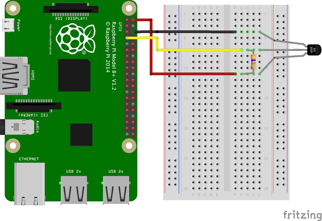
2.ต่อ LED ตาม GPIO ที่ได้เขียนไว้ใน Code
3.แชร์ Wifi จากโทรศัพท์ของเรา
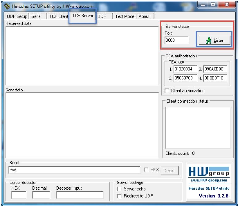
4.ทดสอบเข้า IP ของ ESP8266 ด้วย Browser
5.ลองกด Switch LED ON ,LED OFF
Code
#include
#define LED D0 //กำหนดขาที่ต่อ LED เป็นขา D0
const char* ssid = "sleep"; //กำหนด SSID (อย่าลืมแก้เป็นของตัวเอง)
const char* password = "22222222"; //กำหนด Password(อย่าลืมแก้เป็นของตัวเอง)
unsigned char status_led = 0; //กำหนดตัวแปร ที่เก็บค่าสถานะของ LED
WiFiServer server(80); //กำหนดใช้งาน TCP Server ที่ Port 80
void setup() {
Serial.begin(115200); //เปิดใช้ Serial
pinMode(LED, OUTPUT); //กำหนด Pin ที่ต่อกับ LED เป็น Output
Serial.println();
Serial.println();
Serial.print("Connecting to ");
Serial.println(ssid);
WiFi.begin(ssid, password); //เชื่อมต่อกับ AP
while (WiFi.status() != WL_CONNECTED) //รอการเชื่อมต่อ
{ delay(500);
Serial.print(".");
}
Serial.println("");
Serial.println("WiFi connected"); //แสดงข้อความเชื่อมต่อสำเร็จ
server.begin(); //เปิด TCP Server
Serial.println("Server started");
Serial.println(WiFi.localIP()); // แสดงหมายเลข IP ของ Server
}
void loop() {
WiFiClient client = server.available(); //รอรับ การเชื่อมต่อจาก Client
if (!client) { //ถ้าไม่มี Client เข้ามาให้เริ่มกับไปวน loop รอรับใหม่
return;
}
Serial.println("new client");
while (!client.available())
{
delay(1);
}
String req = client.readStringUntil('\r'); //อ่านค่าที่ได้รับจากclient จากข้อมูลแรกถึง ‘\r’
Serial.println(req); //แสดงค่าที่ได้รับทาง Serial
client.flush();
if (req.indexOf("/ledoff") != -1) //ตรวจสอบว่า data ที่เข้ามามีข้อความ”/ledoff”หรือไม่
{
status_led = 0; //ถ้ามีให้กำหนดค่า ในตัวแปรใน status_led=0
digitalWrite(LED, HIGH); //ให้ LED ดับ
Serial.println("LED OFF");
}
else if (req.indexOf("/ledon") != -1) //ตรวจสอบว่า data ที่เข้ามามีข้อความ”/ledon”หรือไม่
{
status_led = 1; //ถ้ามีให้กำหนดค่า ในตัวแปรใน status_led=1
digitalWrite(LED, LOW); //ให้ LED ติด
Serial.println("LED ON");
}
String web = "HTTP/1.1 200 OK\r\nContent-Type: text/html\r\n\r\n";
web += "\r\n";
web += "\r\n";
web += "
LED Status
\r\n";
web += "
\r\n";
if(status_led==1)
web += "LED On\r\n";
else
web += "LED Off\r\n";
web += "
1.DS18B20 Sensor
2.Raspberry Pi Board
3.Resistor 10k
สามารถ ทำได้ตามการทดลองดังนี้
sudo apt-get update
sudo apt-get install python-dev
sudo apt-get install python-rpi.gpio
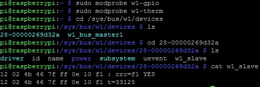
sudo nano /boot/config.txt
you will see some syntax like this.
dtparam=i2c0=on
dtparam=spi=on
dtparam=is2=on
dtoverlay=w1-gpio
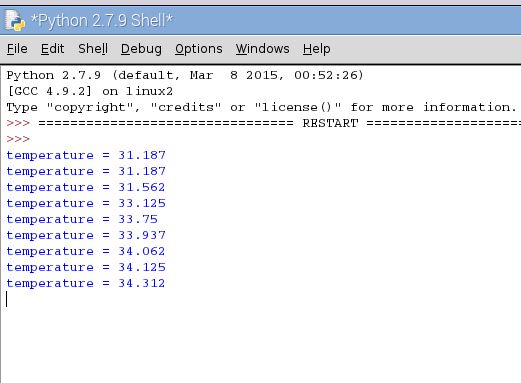
การทดลองอ่านค่าจาก DS18B20 เพื่อส่งอุณหภูมิจาก Raspberry Pi
เข้าไปยัง Web Thingspek เพื่อรู้ว่าอุณหภูมิที่ ตำแหน่งของบอร์ด
Raspberry Pi มีกี่องศา อาจใช้ส่งข้อมูลอุณหภูมิระยะไกลได้
อุปกรณ์
1.Raspberry Pi Board
2.DS18B20 Sensor
3.Resistor 10k
Raspberrypi Temperature ThingSpeak
sudo nano /boot/config.txt
แก้ไขที่บรรทัด #dtoverlay=w1-gpio and เอาcommentออก dtoverlay=w1-gpio
การทดลองนี้ใช้ทำเพื่อควบคุม LED เปิดปิดไฟจาก Web Browser
อาจใช้ในการทดลองจากระยะไกล ที่เราสามารถเข้า Internet
โดยมีบัญชี  Thingspeak ก็สามารถเข้าไปควบคุมหลอดไฟ LED
ได้ครับผม


 Per Akt's Thanachai